
Installing the Stator and Rotor
Note: Do not remove the protective tape wound around the rotor! It has a specific function in the assembly of the PVL ignition.
 After removing the existing magneto from the engine, fix the PVL stator (is vendor-type-specific) to the stator of the motor housing. Make sure that the mounting screws for the stator mount at any point of the motor housing (“sitting on block”, these are dangerous voltages!). If this happens, the stator plate may be damaged or destroyed. If necessary, file or grind the ends of the screws if they are too long. Leave the stator mounting screws a little loose at first. If an additional adapter plate (between stator and housing, for example, when installed in Simson S51) is attached, the adapter plate (item 6) should be designed to ensure a secure connection between the stator and motor housing, otherwise due to vibration can cause damage.
Hint:

Clean before the assembly of the rotor (item 7), both the bore of the rotor and the side pin of the crankshaft with contact cleaner, acetone or another suitable product to ensure that they are clean and free of grease, oil or other deposits is.
Put the rotor on the crankshaft, so that the protective strip stays on the rotor! The matching rotor (type of vehicle-related) should now be pushed without resistance or obstruction to the crankshaft (pin side). Attention should be paid to proper fit of the key (key) in the slot in the side pin. Never hit the rotor with force! The key is only used to prevent distortion and for correct positioning of the crankshaft drive. In rotor types without grooves this is by design of the vehicle manufacturer, and do not require any groove or keyway. The torsional force is transmitted exclusively via the cone (conical seat).
Note 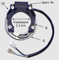
When using an adapter plate (not supplied) between the motor housing and PVL stator plate (item 9), the axial position of the rotor can be placed so that the rotor magnets axially align centrally located to the Stators arm (item 8). The rotor must be radially enough slack i.e. it should not rub against the stator. The axial position of the rotor is obtained from the design thickness of the adapter plate
Too little backlash (rotor jams) between the rotor and the sides of the stator (Item 10), loosen using a Torx screwdriver or use the four screws that secure the stator coil to the stator. When the rotor fits properly without the Torx screws loosening, go directly to the ignition timing. You must now complete the alignment process, if necessary loosen the Torx screws. Press the stator sides with your fingers (do not use pliers or screwdriver) against the rotor and tighten the Torx screws. Now you can remove the protective tape from the rotor.
The ignition system must always have good mass conductivity. The black earth cable (item 1) to be the ignition coil (Item 2) must be grounded. The rotor ignition system should never rotate without the built-consumer (spark plug to ground) ! If there is no spark plug inserted, the ignition system has no mass and establishes a surge that can not be derived. This can lead to total failure of the ignition.
Check manually (rotate several times) that the rotor turns (item 7) rotate without rubbing. Check the bearing side of the engine by moving back and wobbling that there is not too much play on the crankshaft. If the side of the motor bearings have too much play it will begin to wobble and rub against the rotor to the stator.
This leads to loosening of the stator plate (item 9) and wear on the rotor surface or magnets and finally total loss of ignition. This can cause risk of engine damage!

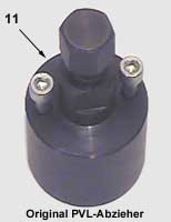
Use only the PVL-puller (special tool, item 11). Failure to follow this instructions may result in damage / destruction of the rotor!
There are four holes on the rotor. These holes are provided for the attachment of optional rotor weights. Only the two holes (Item 12), which are located closest to the center of the rotor are provided for attaching the extractor! Remove the crankshaft nut use this suitable holding device. Never pull the rotor circumference with pliers to hold or twist, this will damage the rotor surface (magnets) and cause ignition malfunctions! Attach the puller into the holes provided in the rotor with the included 6×50 mm screws
Screw the screws completely so that the force cannot ruin the threads. Using an adjustable wrench to prevent it from twisting. Tighten the forcing screw firmly (item 15), which should now touch the end of the crankshaft. If the rotor does not come away from the crankshaft, hit hard with a light hammer on the jack screw to loosen the rotor from the crankshaft.
The current supplied to the digital system PVL digital spark plug (item 16) has a resistance of 5 K and is tested specifically for the digital ignition. This type of connector must be used so that the system works properly. The use of other spark plugs can lead to total failure. Any warranty is void in this case.
While almost all electronic ignitions can withstand moisture during operation, it may be damaged if moisture gets into the turns or they can be damaged by the resulting corrosion. We suggest that you remove the cover to use the magneto ignition, so that the accumulated moisture can evaporate. This is especially the case after the engine is washed with a pressure washer. An additional advantage of this approach is that you can identify any problems that are caused by a faulty seal or a faulty bearing. A faulty bearing side is almost always the destruction of the ignition sequence.
The ignition timing of an engine is directly related to the compression of the engine. The higher the compression, the less the flow (ie flow of the piston at the top dead center or the highest position) can be used for the ignition timing. Since the exhaust pipe, the carburetor, and the cylinder and the cylinder head are attached this can cause a generated amount of heat by the engine, this has to be considered when setting up the ignition timing. It rotates in the heat, that is generated in the combustion chamber.
An engine that burns a particular fuel can only tolerate a certain amount of heat, and all the above factors are related to the amount of heat. The life of an engine is associated with the ignition timing and its effect from the amount of heat, it is important that you work closely. Too much ignition advance, and you overheat the engine, too little, and you give away power. Petrol and alcohol (methanol) have different values ??because of their combustion characteristics. In general, alcohol burns slower than gasoline and requires more heat (cooler combustion, so-called internal cooling with methanol). The power of an engine can be influenced in several ways, including by advancing the ignition timing, or by increasing the compression. But you can only use so much heat / energy, as the engine can withstand. Tuning is a very complex issue for professionals and should only ever be used when you need high performance and the life of the engine does not have a significant value.
Mounting an additional flywheel rotor disc on PVL, Selettra Malossi or Kundo ignitions
On Malossi or Selettra, Kundo or PVL Ignitions there is an option to mount an additional so-called inertia flywheels on the rotor. The Malossi flywheels are included already. In PVL ignitions and Kundo, flywheels can also be mounted, but these are not included in standard delivery. These flywheels are made from high tensile steel and must run and fit one hundred percent with the rotor. The material should be checked for cracks after processing and that they are finely balanced together with the rotor. The fastening screws must be secured with Loctite. At speeds up to 20,000 rev / min the smallest imbalance causes vibrations that can not only destroy the crankshaft bearings, but also to release the flywheel rotor and even the side pin. If wrong material (micro-cracks in the structure) there is a risk that the additional flywheel can be destroyed by the high rotational and centrifugal forces and the generated vibrations caused by the engine itself can cause it possibly to explode.
Warning!
There is a great risk of injury, and we expressly point out that any warranty is excluded. Use only the manufacturer-supplied flywheels.