Installation Instructions for PVL Ignitions
Ignore and not following the information contained in this manual could result in damage to your new ignition and the engine components! Please read all the information contained here and
follow the appropriate instructions. Your engine is an assembly of many machined parts and each part has tolerances that are allowed in the production. Due to these tolerances, it may be necessary to set the magnetic dynamos on your specific engine
Fixing of the ignition coil
There are two versions of the external coil with PVL Ignitions. The ignition coil and the CDI module can be one piece or the ignition coil and the CDI module are two separate parts. If your coil and the CDI module are separate, make sure that the ignition coil is directly grounded (necessary) attach to the chassis or frame. If not, you may be required to produce a small tab that is welded directly to the ground (frame part) of the vehicle. The attachment must be stable, and we recommend the use of lock nuts, to avoid coming loose. The CDI module can be installed anywhere where a 6 mm hole is found, and the wire from the module can be connected to the coil.
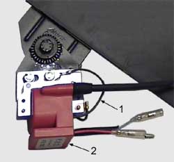
Necessarily ground cable (item 1) of the ignition coil to the frame on a well-grounded place. Without connecting the ground wire there is a danger of overloading and that the total failure of the ignition! Earth (Ground cable) clamp at the coil of the fixing screw.
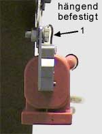
If your coil and the CDI module constitute a unit, you will probably need to modify your bracket to accomodate the PVL coil. This modification may only mean drilling new holes or cutting off the original mounting and welding on a new attachment. During the attachment of the coil to a fixed frame part (plate), it is essential that the mounting plate for the coil is in a vertical plane (vertical) is (straight up and down). When the weight of the coil (screwed laterally) at horizontally mounted coil acts on the mounting plate from above, the weight of the coil, on the holding plate will break, for example due to holes in the ground the weight of the coil greatly increases (acceleration9/81m²)
Make sure that none of the cable comes in contact with the exhaust of your machine. When this happens, the insulation may melt on the wires, which has a short circuit which may result in destroying the ignition system.
For applications with very high vibration levels it is recommended to put insulating tape around the coil in order to avoid vibration. The black ground wire with the ring connector must be grounded on the machine or the engine. If an attachment with a secure device is not possible, you can use any method that holds the coil securely to the frame, such as with cable ties or in a foam sleeve with insulating tape. The black ground wire (Item 1) with ring connector must in turn be grounded to the frame of the machine or engine. The current supplied to the digital system is designed specially for spark plug spark with a 5000 ohm resistor value. This type of connector must be used so that the system works properly.
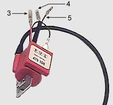
When the coil is mounted, it can be connected to the magneto depending on the type of system one of two ways. The analogue systems use spade lugs and the digital systems molded connectors between the coil and the magneto. The red wire (# 3), which leads out of the coil is to be used as a wire for the kill button (tear-off switch). Any device that can carry current to ground, should be enough for this, but we recommend the use of a device that is designed for use in motor vehicles (eg Quick Stop).