PVL ignition coil ignition timing set at 479 100 1075 or suitable analogy with stator and rotor stator 1077 to crankpin
The analog ignition coil 479100 is powered by analog stators with 3000 turns (the ignition coil a defined base voltage expected). Therefore it is necessary the stator and rotor to be mounted to one another at the correct level. Also the rotor should be about 4 mm on the coil body of the stator, this is also seen in the magnetic cores which are to be in the middle of the core laminations. For ignitions where the rotor is too far out on the crank pin, 4mm can be removed out of the base plate of the stator. For rotors that are too far over the stator this can be either underpinned with an adapter plate, or the rotor can be turned out to a larger degree in accordance with the crankshaft.
In addition, the rotor must be centrally run to the stator and should be clearance between the core laminations (stator arms). Bearing clearances should be allowed to allow certain expansion due to heat when under load. The manufacturing dimensions: outer diameter of the rotor Ø58, 00 mm, inner diameter of the stator Ø59, 00 mm, original 0.5 mm. Often by reducing the play to about 0.1-0.2 mm more firing power is deployed.
If the stator and rotor are mounted at the right level to each other, then the ignition coil will provide the ignition running as based on the speed diagram. Deviations from the installation level influence the ignition timing and ignition.
The ignition coil 479100 is shown in the diagram to the values ??for early, ie the maximum dynamic adjustment in EARLY is the speed which has the highest value in degrees of crankshaft rotation. 479 100 in the case of the ignition coil that is at PVL 4000-6000 rev / min 21.5 ° crank angle.
This means:
If you need a maximum spark at 21 ° BTDC, then in OT, the stator and rotor are aligned to each other and mounted so that the magnetic cores, stator core laminations and an axle opening another form (see PVL Quick Start Guide). The ignition ignites corresponding to the ignition curve as shown in the diagram.
If you specify a maximum ignition advance in e.g. Need 28 ° BTDC, then is set as follows:
desired max. The advance of the engine minus max. dynamic adjustment of the coil = static setting angle. In this case, 28 ° BTDC – 21.5 ° dyn. Adjustment = 6.5 ° entering angle static (negative values ??”ATDC”).
Consequently, at 6.5 ° BTDC stator and rotor are mounted aligned with each other.
The ignition then fires according to the diagram, at 4000-6000 r / min at 28 ° BTDC (21.5 ° + 6.5 ° static dynamic adjustment setting angle).
If you e.g. at 10,000 rev / min require an ignition timing at 26 ° BTDC, you must deduct the value from the chart at 10,000 rev / min (18 ° CA). You therefore calculate the required advance 26 ° (at 10000 rev / min) minus dynamic adjustment 18 ° (at 10000 rev / min)
= 8 ° static setting angle, in which the stator and rotor must be aligned to each other. Note the ignition timing at 4000-6000 r / min = 29.5 ° BTDC (21.5 ° +8 ° BTDC)
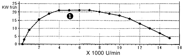
[1] Max. Ignition timing for early, 21,5° KW bei 4000-6000 U/min