PVL Ignition Instructions manual
Fit the ignition coil together with the core sheet package to the chassis frame; additionally, silent blocks may be used to absorb vehicle vibrations and shocks. Establish a good earth connection between engine block and chassis by using an earth cable of at least 4mm².
Note: Silent blocks must be bridged with a separate earth cable!, otherwise within a few seconds the Electronic will be interrupted. Do not at any time bend the ignition coil bracket.
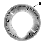
Fit the stator via the three slots in the crankcase. Vehicles originally not fitted with PVL racing ignitions may require a purpose-made adapter plate (non-magnetic material, if possible non-heat-transmitting to protect stator against heat from the engine).
Place rotor on lateral pin of crankshaft. Remove any dirt beforehand, and remove grease from crankshaft stub and rotor inner cone. Ensure that the rotor has a close fit; if necessary lap in rotor onto lateral pins using abrasive paste. If no Woodruff key is used, please pay attention to the position of the crankshaft, rotor and stator – see “Ignition Timing”.
 Connect all necessary mass cables of the ignition. Connect the stator connection with the ignition coil. Connect the ignition switch (red connection) and, at the ignitions with two ignition curves, the ignition curve selector switch (green connector). As ignition curve commuter in track racing often a cutout switch is used.
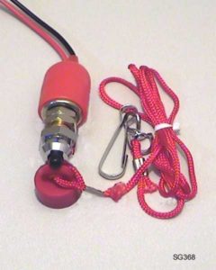
Function of the cutout switch (Quickstop, emergency-off): If the red connection cable is connected to mass, the ignition is switched off. If it is not connected, the ignition is ready for operation.
 At ignitions with two ignition curves, the first ignition curve is activated, when the green connecting cable is connected to mass. If the cable is not connected, the second ignition curve is active. The PVL ignitions allow to switch over between the ignition curves during operation.
For the digital ignition systems a radio-shielded spark plug connector with 5 kOhm is required! Alternatively the radio-shielded spark plugs as for example DENSO Iridium Power can be used, they are available in the Webshop.
Screw the spark plug connector into the ignition cable and plug the spark plug connector on the installed spark plug.

Examples of calculations from cycle times calculation V1.1 (Christoph Köhler):
| Beispiel-Berechnungen aus Steuerzeiten-berechnung V1.1 (Christoph Köhler): | ||
| Motor Typ | Grad-Kurbelwinkel vor O.T. | Kolbenposition in mm vor O.T. |
| 500cc Motorbike Stroke 86 mm Rod length 160 mm |
10° | 0,8 mm |
| 20° | 3,2 mm | |
| 30° | 7,2 mm | |
| 250cc Motorbike Stroke 68 mm Rod length 130mm |
10° | 0,5 mm |
| 20° | 2,7 mm | |
| 30° | 5,6 mm | |
| 125cc Motorbike Stroke 54 mm Rod length 110mm |
10° | 0,5 mm |
| 20° | 2,0 mm | |
| 30° | 4,4 mm | |
| 50cc Moped Stroke 44 mm Rod length 85mm |
10° | 0,4 mm |
| 20° | 1,6 mm | |
| 30° | 3,6 mm | |
| 50cc Scooter Stroke 40 mm Rod length 80 mm |
10° | 0,4 mm |
| 20° | 1,5 mm | |
| 30° | 3,3 mm | |
| Details without warranty! | ||
To measure the PVL ignition timing we recommend the stroboscopic flashlamp of Bosch art.no. 0 684 100 309 – 424
Setup of the Ignition
On vehicles which are equipped with original PVL racing ignitions, a disc spring in the tailshaft means that the rotor is always properly positioned on the crankshaft. The stator is positioned as specified by the engine manufacturer in the crankcase, set the static ignition timing according to the engine manufacturer by turning the stator.
For vehicles that are converted to PVL Racing, you need:
Max. advance in degrees crank angle according to engine manufacturer or tuning stage
Max advance the PVL ignition advance curves according to diagram
Align the rotor stator:
When using the disc spring in tailshaft the rotor is fixed in place. The stator is secured in the crankcase, that the desired pre-ignition is achieved. Rotate the crankshaft to the desired position before TDC Fix this position and twist the stator so that the marks are on the stator and the rotor cover. In analog systems such as 105 458 or 479 100 is the max. Dynamic advance achieved if the markings of the rotor and stator cover.
In digital systems, such as 500 106 or 500 134 is the max. Advance to identify the Zündkurvendiagramm. Since the ignition curves differ serious it is not possible to create a general setup instructions. Do not ignore the special setting instructions for digital PVL system on the following pages.
Align the rotor to the stator
Since the rotor is applied only in rare cases with disc spring, the rotor is aligned with the stator. Mount the stator into the crankcase. Take into account a suitable cable routing from the motor housing. Fasten the stator so that the screws are in the slots are oriented approximately in the middle. This gives you the opportunity afterwards to adjust the ignition timing fine without pulling the rotor over again. Rotate the crankshaft to the desired position before TDC and fix this position (piston stop). Put the rotor to rotate it so the tailshaft, until the indications of stator and rotor cover. Screw the rotor in this position. Loosen the crankshaft locking and check the setting. By rotating the stator to adjust the ignition still fine.
In analog systems such as 105 458 or 479 100 is the max. Dynamic advance if the markings of the rotor and stator are covered In digital systems, such as 500 106 or 500 134 is the max. Advance to identify the Ignition curve diagramm. Since the ignition curves can differ, it is not possible to create a general setup guide. Do not ignore the special setting instructions for digital PVL system on the following pages. Generally all stators for left-and right-turning motors are suitable.
However, not all stators for the rotation have a marker. It must therefore be distinguished between stators:
- clockwise, a mark on the right stator arm.
- left-and right-handed, two markers about 180 ° opposite.
- only clockwise, a mark on the right-stator arm.
The rotors are distinguished only by the twisted cone. The magnetic poles, and the label is always the same.